How Does Air Flow Through a Diesel Engine?
The journey of air through a diesel engine represents a precisely engineered process that directly determines combustion efficiency, power output, and emissions control. Understanding this airflow path is essential for recognizing how a properly functioning Diesel air intake system contributes to optimal engine performance and fuel economy. From initial intake to final exhaust, air undergoes significant transformations in pressure, temperature, and velocity that ultimately define the engine's operational characteristics and efficiency.
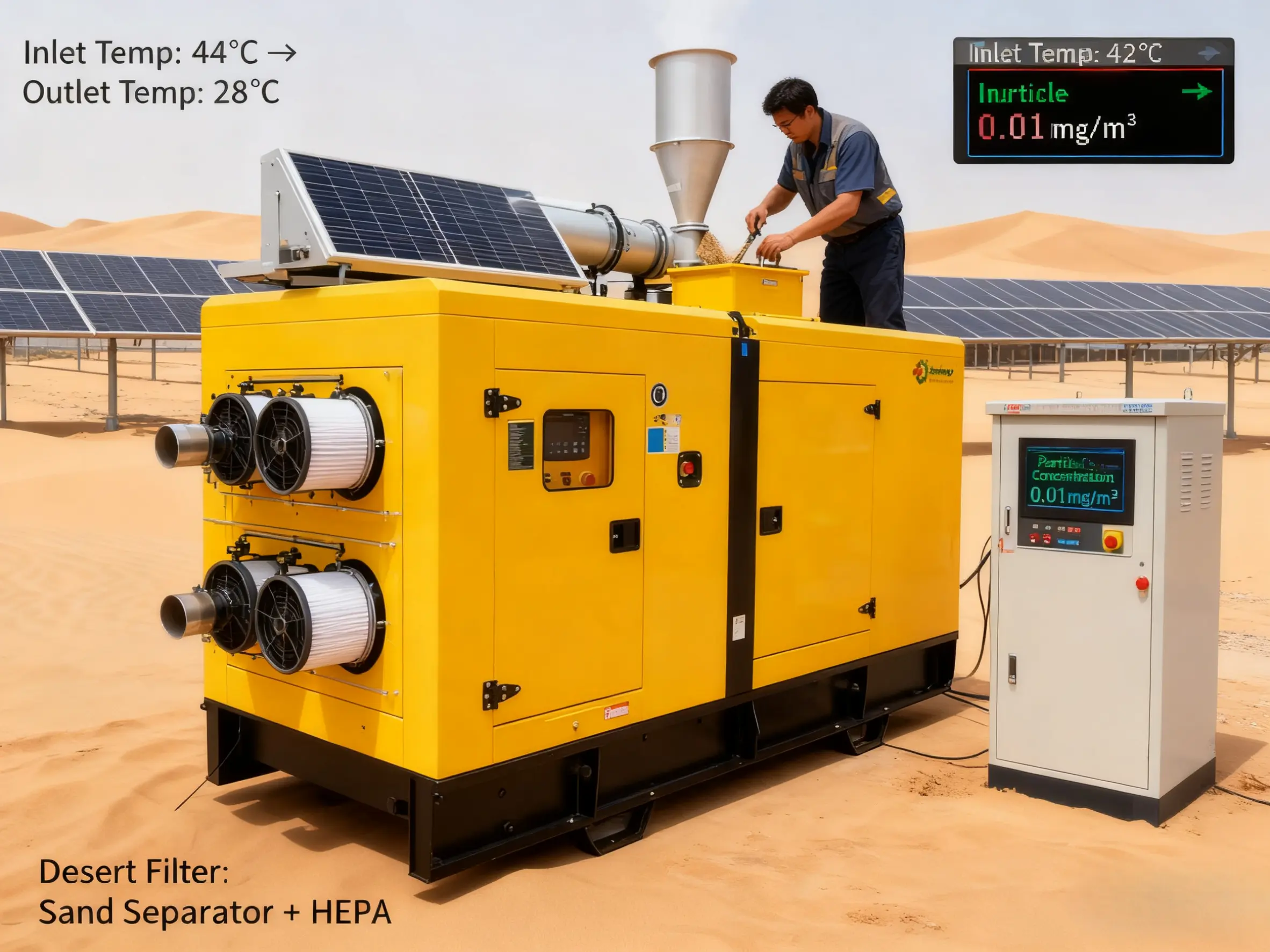
Complete Airflow Pathway
Air follows a carefully designed path through the engine system:
Initial Intake Phase:
Ambient air enters through weather-protected intake hood
Air passes through multi-stage filtration systems
Initial cleaning removes larger particulates and debris
Directional vanes guide airflow while preventing water ingress
Filtration and Conditioning:
Primary filter captures particles down to 10 microns
Secondary safety filter provides backup protection
Pre-cleaners separate heavier contaminants through cyclonic action
Filter restriction indicators monitor accumulating resistance
Compression Stage:
Turbocharger compressor wheel accelerates incoming air
Air pressure increases while temperature rises significantly
Kinetic energy converts to pressure energy in volute housing
Compressed air moves toward charge air cooling system
Temperature Management:
Hot compressed air enters intercooler or aftercooler
Heat exchange reduces air temperature by 100-200°F
Cooler, denser air contains more oxygen molecules
Dense air proceeds to intake manifold distribution
Core Components and Their Functions
Each component plays a critical role in managing airflow:
Air Filter Assembly:
Multi-layer filtration media ensuring clean air supply
Housing designed for even airflow distribution
Water separation mechanisms preventing liquid intake
Service indicators monitoring filter condition
Turbocharger System:
Compressor wheel increasing air pressure 2-4 times atmospheric
Bearing system supporting high-speed rotation
Wastegate or VGT mechanisms regulating boost pressure
Oil supply providing lubrication and cooling
Intercooler Technology:
Extended surface area maximizing heat transfer
Internal fins creating turbulent airflow for better cooling
Pressure-rated tanks containing boosted air
Mounting system resisting vibration and stress
Intake Manifold:
Equal-length runners ensuring balanced cylinder charging
Smooth internal surfaces minimizing flow resistance
Integrated ports for sensors and auxiliary systems
Robust construction containing boost pressure
Air State Transformations
Air undergoes significant physical changes throughout the system:
Pressure Evolution:
Atmospheric pressure at initial intake (14.7 psi at sea level)
Moderate vacuum created by turbocharger suction
Boost pressure development through compressor action
Final pressure at cylinder entry (typically 20-45 psi)
Temperature Progression:
Ambient temperature at system entry
Temperature increase through compression (up to 300°F)
Significant cooling through intercooler (down to 130°F)
Final temperature optimization for combustion
Density Optimization:
Natural density at atmospheric conditions
Reduced density through heating during compression
Restored density through intercooler temperature reduction
Final density providing maximum oxygen concentration
Velocity Variations:
Moderate velocity through initial intake components
High velocity through turbocharger compressor
Controlled velocity in intercooler passages
Optimized velocity for cylinder filling in manifold
Combustion Relationship
Airflow characteristics directly impact combustion efficiency:
Oxygen Availability:
Denser air provides more oxygen molecules per volume
Adequate oxygen enables complete fuel combustion
Optimal air-fuel ratios typically 18:1 to 22:1
Oxygen surplus preventing smoke and particulate formation
Combustion Quality:
Proper air swirl ensuring thorough fuel mixing
Turbulence supporting rapid and complete burning
Temperature management preventing premature ignition
Pressure characteristics influencing combustion pressure
Emission Control:
Complete combustion minimizing particulate matter
Optimal temperatures reducing NOx formation
Efficient burning decreasing hydrocarbon emissions
Proper airflow preventing incomplete combustion products
System Optimization Strategies
Enhancing airflow system performance:
Component Upgrades:
High-efficiency air filter elements reducing restriction
Enhanced intercoolers improving temperature drop
Low-restriction intake piping minimizing flow losses
Advanced turbocharger technology for better response
Maintenance Optimization:
Regular filter replacement preventing airflow restriction
System cleaning maintaining component efficiency
Leak detection ensuring pressure integrity
Sensor calibration guaranteeing accurate monitoring
Operational Improvements:
Proper warm-up procedures ensuring thermal stability
Load management preventing excessive demand
Environmental considerations adapting to conditions
Monitoring systems providing performance feedback
Maintenance Essentials
Preserving optimal airflow system function:
Preventive Maintenance:
Air filter inspection every 250 operating hours
Complete system check every 500-1000 hours
Pressure testing during major service intervals
Component replacement per manufacturer specifications
Performance Monitoring:
Tracking boost pressure for system health
Monitoring intake temperatures for cooling efficiency
Observing fuel consumption for combustion quality
Recording maintenance activities for trend analysis
Problem Identification:
Recognizing early signs of airflow restriction
Identifying turbocharger performance issues
Detecting intercooler efficiency degradation
Noticing intake leak symptoms
Conclusion
The journey of air through a diesel engine represents a sophisticated process where each component contributes to delivering clean, dense, cool air for optimal combustion. Understanding this Diesel air intake system process helps operators maintain peak engine performance, maximize fuel efficiency, and extend engine service life. Proper maintenance and timely attention to airflow system components ensure reliable operation and prevent performance degradation over time.
Our technical team specializes in diesel engine airflow systems and can provide expert guidance on maintenance, optimization, and performance improvement. Contact us at skala@whjlmech.com for professional assistance with your diesel power system requirements.
References
Society of Automotive Engineers. (2023). SAE J1939: Serial Control and Communications Vehicle Network. Warrendale: SAE.
International Organization for Standardization. (2022). ISO 5011:2014 Inlet air cleaning equipment for internal combustion engines and compressors. Geneva: ISO.
Heywood, J.B. (2023). Internal Combustion Engine Fundamentals. New York: McGraw-Hill Education.
Johnson, M. (2022). Emergency Power Systems: A Comprehensive Guide to High-Speed Diesel Generators. Power Engineering Quarterly, 45(3), 78-92.


